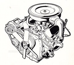
V4 1,5 & 1,7l "Köln" / "Cologne"
Engine data:
OHV engine with camshaft located in the engine block. Cast iron engine block and cylinder heads. The camshaft and an axuliary shaft are driven by spur gears. The valves are operated by solid tappets, push rods and valve levers.
Installed in:
P4, P5, P6, P7, Capri MK1, Transit MK1
Notice:
This engine was first installed in the 12M (P4) in 1962 as an "Open Deck" version which had free-standing cylinder liners and a open water jacket.
The matching "Open Deck" cylinder heads had a spark plug thread length of 12,7mm.
In November 1967, the so-called "closed deck" engines, were introduced. These can be identified by their spark plug thread length of 19,0mm.
Engine Variants Installed In This Car
| Engine | Power | Engine Code | Year | Comment |
| V4 1,5l | 44kW / 60HP | EX | 08/68-01/72 | LC-engine |
| V4 1,7l | 48kW / 65HP | MX | 08/68-01/72 | LC-engine |
| V4 1,7l | 51kW / 70HP | MY | 08/68-01/72 | HC-engine |
Engine Code Location & Cylinder Head Identifier

Cylinder Head Identifier
| Engine | Letter |
| V4 1,2l | B |
| V4 1,3l | BC |
| V4 1,5l | A |
| V4 1,7l | A |
Adjusting Values

Tightening Order
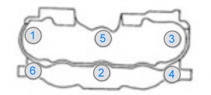
Tighten the screws in the order shown in the illustration. Start with about half of the specified value and increase to the final value.
| Anzugsmoment | Nm |
| Zylinderkopf | 90-110 |
| Ansaugkopf | 21-25 |
| Auspuffkrümmer | 21-25 |
| Ventildeckel | 5-8 |
| Zündkerzen | 30-40 |
| Ölablassschraube | 21-28 |
Zündreihenfolge
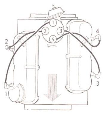
Cylinder 1 front right in the direction of driving
Firing order 1-3-4-2
Ignition distributor rotates clockwise
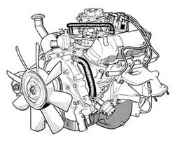
V6 1,8 - 2,6l "Köln" / "Cologne"
Engine data:
OHV engine with camshaft located in the engine block. Cast iron engine block and cylinder heads. The camshaft is driven by spur gears. The valves are operated by solid tappets, push rods and valve levers.
Installed in:
P5, P7, Capri, Taunus, Granada, Sierra, Scorpio, Transit
Notice:
This engine was introduced in 1964 in the 20M (P5) and was designed as an "open deck" engine with free-standing cylinder liners and an open water jacket.
In this version, spark plugs with a thread length of 12.7mm are installed.
A technical change took place in May 1967 and from the 20M (P7) onwards, the "closed deck" engine with a closed water jacket was installed and equipped with cylinder heads with a spark plug thread of 19.0 mm.
In October 1969 Ford redesigned the cooling system and replaced the external water pump by a central pump with the shape of a "sea-horse".
This engine was used in many models until 1996 and was also provided with various injection systems. As 2,9i in the Scorpio "RS Cosworth" it developed up to 207 hp.
Engine Variants Installed In This Car
| Engine | Power | Engine Code | Year | Comment |
| V6 1,8l | 60kW / 82HP | 8 | 08/68-10/69 | HC-engine |
| V6 1,8l | 60kW / 82HP | RY | 10/69-01/72 | HC-engine |
| V6 2,0l | 62kW / 85HP | L | 08/68-10/69 | LC-engine |
| V6 2,0l | 62kW / 85HP | NX | 10/69-01/72 | LC-engine |
| V6 2,0l | 66kW / 90HP | - | 08/68-10/69 | HC-engine |
| V6 2,0l | 66kW / 90HP | NY | 10/69-01/72 | HC-engine |
| V6 2,3l | 79kW / 108HP | 3 | 08/68-10/69 | HC-engine |
| V6 2,3l | 79kW / 108HP | YY | 10/69-01/72 | HC-engine |
| V6 2,3l | 92kW / 125HP | YZ | 10/69-01/72 | HC-engine |
| V6 2,6l | 92kW / 125HP | UZ | 10/69-01/72 | HC-engine |
Engine Code Location & Cylinder Head Identifier
Cylinder Head Identifier
| Engine | Year | Letter |
| V6 1,8l | 08/68-10/69 | |
| V6 1,8l | 10/69-01/72 | BN |
| V6 2,0l | 08/64-05/67 | |
| V6 2,0l | 05/67-10/69 | C |
| V6 2,0l | 10/69-06/79 | CN |
| V6 2,0l | 06/79-08/81 | C9 |
| V6 2,0l | 08/81-02/87 | |
| V6 2,3l | 05/67-10/69 | A |
| V6 2,3l | 10/69-06/79 | AN |
| V6 2,3l | 06/79-02/87 | A9 |
| V6 2,4l | 09/86-09/88 | |
| V6 2,4l | 10/88-10/94 | |
| V6 2,6l | 10/69-01/72 | DN |
| V6 2,8l | 09/76-12/88 | EN |
| V6 2,9l | 01/86-02/93 |
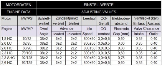
Adjusting Values
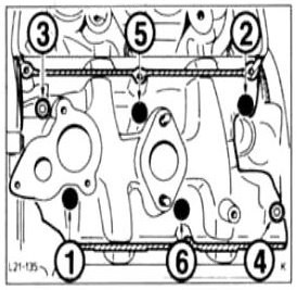
Tightening Orders
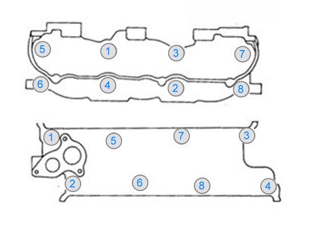
Tighten the screws in the order shown in the illustration. Start with about half of the specified value and increase to the final value.
| Tightening Torque | Nm |
| Cylinder head | 95-115 |
| Intake manifold | 21-25 |
| Exhaust manifold | 21-25 |
| Valve cover | 5-8 |
| Spark plugs | 30-40 |
| Oil drain plug | 21-28 |
Firing Order

Cylinder 1 front right in the direction of driving
Firing order 1-4-2-5-3-6
Ignition distributor rotates clockwise